Home › Unlabelled ›
Motor Control Circuit Wiring Diagram / Interpretation And Application Of Simple Wiring And Elementary Diagrams - Neon led circuits for car schematic circuit diagram.
Motor Control Circuit Wiring Diagram / Interpretation And Application Of Simple Wiring And Elementary Diagrams - Neon led circuits for car schematic circuit diagram.. In the circuit diagram shown, the switch s1 is on and switch s2 is off. 3ø wiring diagrams diagram dd1. They can be used as a guide when wiring the controller. A distinction is drawn between Ladder diagram basics #3 (2 wire & 3 wire motor control circuit).
I then moved the wires around to follow the one in the real pictures of the circuit and it worked. Wiring diagrams show the connections to the controller, while line diagrams show circuits of the operation of the controller. Most on/off motor control circuits in the united states are some variation on this wiring theme, if not identical to it. I want star delta power and control wiring diagram with full detail if you give me this please full drawing means from starting to end point like as no/nc of timer and connector please give on my mail id. 3 phase motor reverse forward control wiring tutorial | rig electrician training.
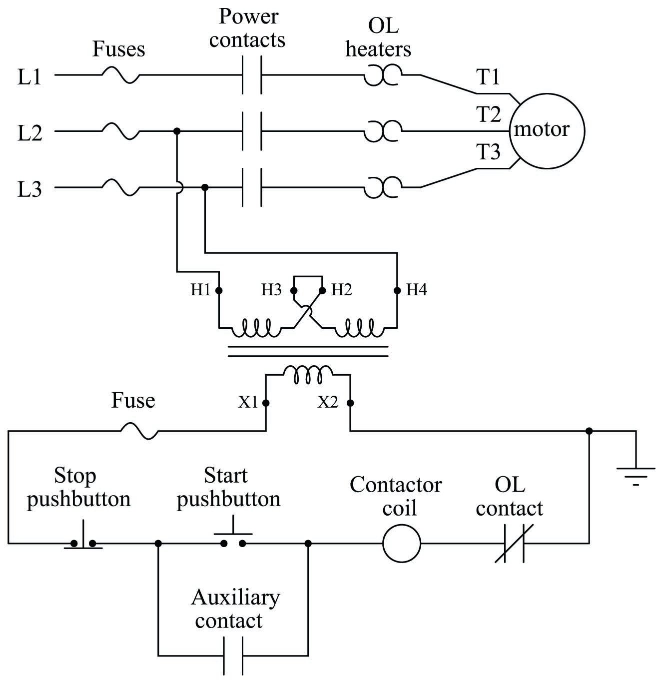
Schematic Control Diagram Wiring Library from www.v6z24.com How to do contactor wiring for 3 phase induction motor with 3 pole circuit breaker, overload relay, no, nc push button switches. Ladder diagram basics #3 (2 wire & 3 wire motor control circuit). Arduino dc motor control circuit: A simple ladder diagram showing the interconnections of all components in this motor control circuit makes this system easier to understand: Contactor wiring for 3 phase motor with circuit breaker, overload relay diagram, normally open and normally close push button switch diagram. They can be used as a guide when wiring the controller. Pwm mushroom motor control with tl494 schematic circuit diagram. The basic control circuits include two wire, three wire controls, manual /automatic, sequential control, stop/start, forward reverse, and jogging configuration 1 illustrates a switch connected to a motor starter coil which turns on a motor or resistive load not shown in control diagrams.
A wide variety of wiring diagram motor control options are available to you, such as usage, local service location, and protect feature.
Connection diagrams, or wiring diagrams, show the components of the control circuit in a semblance of their actual physical locations. Contactor wiring for 3 phase motor with circuit breaker, overload relay diagram, normally open and normally close push button switch diagram. The wiring diagrams and line diagrams presented illustrate the many ways in which eatons full voltage and reduced voltage motor starters can be used in everyday circuit applications. How to do contactor wiring for 3 phase induction motor with 3 pole circuit breaker, overload relay, no, nc push button switches. Here is a simple pwm motor speed controller circuit that can be used for varying the speed of low power dc motors. Wire looms, control panels, special electrical conrol equipment. Wiring for hand control and radio control. Ladder diagram basics #3 (2 wire & 3 wire motor control circuit). Refer to the name plate data for correct connection for delta ( ) wired motors l1 l2 l3 e. Motor control examples and block diagrams. I then moved the wires around to follow the one in the real pictures of the circuit and it worked. What exactly is pulse width modulation? The top countries of supplier is china, from which the.
The top countries of supplier is china, from which the. Typically, wires in control systems are marked with numbers and/or letters for identification. The correct wiring should be: There are 210 suppliers who sells wiring diagram motor control on alibaba.com, mainly located in asia. Hand control & horn relay board.
On Off Electric Motor Control Circuits Discrete Control System Elements Automation Textbook from control.com They can be used as a guide when wiring the controller. Ladder diagram basics #3 (2 wire & 3 wire motor control circuit). The top countries of supplier is china, from which the. In this video i will teach you step by step how make wiring for 3 phase motor control circuit by using magnetic contactor and thermal overload relay. Here's a simple pwm based motor speed controller circuit which can be used for controlling a the circuit also provides an instant bidirectional stop and reversal of the motor rotation by a single the above frequency from pin#3 of ic1 is fed to pin#2 of ic2 which is wired as a standard monostable. Typically, wires in control systems are marked with numbers and/or letters for identification. Here is a simple pwm motor speed controller circuit that can be used for varying the speed of low power dc motors. Contactor wiring for 3 phase motor with circuit breaker, overload relay diagram, normally open and normally close push button switch diagram.
Project circuit schematic diagram is the one below.
Motor control examples and block diagrams. This page contain electronic circuits about motor control circuits at category motor control circuit : The speed of the dc motor (both directions) is controlled with the 10k potentiometer which is connected to analog channel 0 (a0) and the direction of rotation is controlled with the push button. Project circuit schematic diagram is the one below. How to do contactor wiring for 3 phase induction motor with 3 pole circuit breaker, overload relay, no, nc push button switches. In dual spdt motor driver circuit, the dc motor terminals are connected between the common poles of the two relays. The circuit diagram for the arduino stepper motor control project is shown above. A multitude of other circuit combinations, not shown, should become apparent when reviewing the diagrams. Meddings engineering will provide customers with many different products including: Arduino dc motor control circuit: Refer to the name plate data for correct connection for delta ( ) wired motors l1 l2 l3 e. I then moved the wires around to follow the one in the real pictures of the circuit and it worked. The schematic diagram shows that with the motor operating in one direction, a contact on the speed switch opens the control circuit of the starter used for the opposite direction.
The rule is, all permanently connected (electrically common) points must bear the same. 3 phase motor reverse forward control wiring tutorial | rig electrician training. A wide variety of wiring diagram motor control options are available to you, such as usage, local service location, and protect feature. Hand control & horn relay board. In dual spdt motor driver circuit, the dc motor terminals are connected between the common poles of the two relays.
Diagram Electric Motors Control Diagram Self Starter University Full Version Hd Quality Starter University Venndiagramgraphic Ordoequestristempliarcadia It from i2.wp.com Contactor wiring for 3 phase motor with circuit breaker, overload relay diagram, normally open and normally close push button switch diagram. Arduino dc motor control circuit: In this video i will teach you step by step how make wiring for 3 phase motor control circuit by using magnetic contactor and thermal overload relay. Hand control & horn relay board. Three phase motor connection schematic, power and control wiring installation diagrams. In dual spdt motor driver circuit, the dc motor terminals are connected between the common poles of the two relays. Here is a simple pwm motor speed controller circuit that can be used for varying the speed of low power dc motors. A simple ladder diagram showing the interconnections of all components in this motor control circuit makes this system easier to understand:
This page contain electronic circuits about motor control circuits at category motor control circuit :
The speed of the dc motor (both directions) is controlled with the 10k potentiometer which is connected to analog channel 0 (a0) and the direction of rotation is controlled with the push button. On this page we'll go into a bit of detail. 3ø wiring diagrams diagram dd1. There are 210 suppliers who sells wiring diagram motor control on alibaba.com, mainly located in asia. Arduino dc motor control circuit: The wiring diagrams and line diagrams presented illustrate the many ways in which eatons full voltage and reduced voltage motor starters can be used in everyday circuit applications. Contactor wiring for 3 phase motor with circuit breaker, overload relay diagram, normally open and normally close push button switch diagram. 3 phase motor reverse forward control wiring tutorial | rig electrician training. Most on/off motor control circuits in the united states are some variation on this wiring theme, if not identical to it. How does pwm motor control work, and what does a pwm circuit look like? Motor control examples and block diagrams. I want star delta power and control wiring diagram with full detail if you give me this please full drawing means from starting to end point like as no/nc of timer and connector please give on my mail id. Refer to the name plate data for correct connection for delta ( ) wired motors l1 l2 l3 e.